| Designs |
|
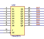
The expansion POD interface uses a transparent buffer U12 which latches the 8 logic levels for writing into the SRAM buffer via the digital data bus. 

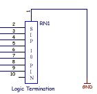
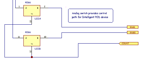
This buffer has an optional input pulldown resistor network RN1 which is nominally 100K. The pulldowns ensure that if nothing is connected to a POD input it floats to ground. It also means the input impedance is 100K. If your application requires a higher input impedance, RN1 may be omitted without detriment to the design. Analog switch U22 connects RNG0 and RNG1 signals from the PIC to the Logic POD.  These signals are active during SHIFT mode and enable serial communications with a "Smart Ports" via the IO-0 and IO-1 pins on the Logic POD connector. Vraw+, Vraw- are available through 500 mA poly fuses at the POD connector. This allows external POD devices to be powered from the BitScope itself. +5 regulated is also available. Also 2 analog signals are brought in via the Logic POD. These are the 3 rd and 4 th analog channels (selected via PG0 option in Spock). These signals have analog grounds which should not be connected to digital grounds. Logic POD IdeasThe following ideas suggest uses for the Logic/Expansion POD connector. The minimum "POD" is just a 25 way ribbon cable terminated by a pin header for connecting probes to the circuit under test. A more sophisticated example is our own Proto POD. The I/O control signals make it possible to have "smart POD" devices that can provide extra functionality.
|
Copyright © 2023 BitScope Designs