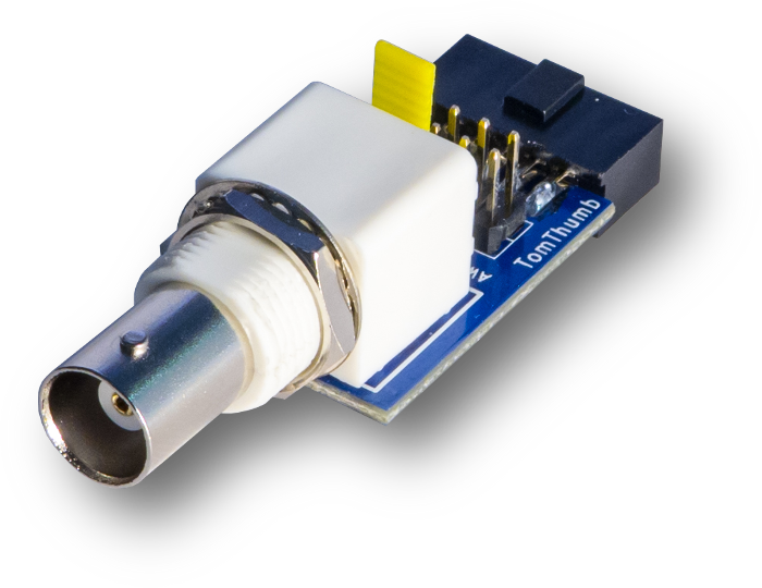
BitScope MP02 is an inline BNC adapter for BitScope Micro. It's designed for use with oscilloscope probes and coaxial cables.
We call it BitScope Tom Thumb: a flexible in-line mixed signal adapter solution for BitScope Micro.
MP02 replicates the BitScope Micro Diagnostic Port on the 10-pin header mounted behind the BNC socket so full access to all the BitScope signal inputs and outputs remain available.
MP02 provides full access to all the features of BitScope Micro while adding the ability to monitor or generate signals via the BNC channel. It supports switching the BNC channel between the CHA analog input, the built-in waveform generator and logic channel 4. It's even possible to connect other port adapters designed for BitScope Micro via Tom Thumb.
MP02 makes it possible to use standard oscilloscope probes with BitScope Micro.
Passive probes that have 1:1, 10:1, 100:1 or other attenuation ratios can be used. It also supports active differential probes, current probes and most other types of probe which are BNC terminated and designed for use with standard scope inputs.
This is possible because despite its tiny size and appearance, BitScope Micro has electrically compatible analog inputs with 1MΩ/20pF impedance so compensation circuits in standard probes will work the same with BitScope Micro and MP02.
If you need to connect two oscilloscope probes at once we recommend Hammerhead (MP01) instead.
MP02 is not just for oscilloscope probes. It also allows the use use BNC terminated cables for connection with other equipment that uses this common standard.
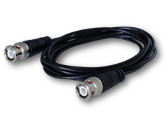
This makes MP02 ideal for data acquistion and related applications where RG-58 cabling with BNC termination is commonly used. If an application requires 50Ω termination, pass-through terminators like PAC-01 are available.
In addition to the BNC connected analog inputs, MP02 provides connections for BitScope Micro's six logic inputs and waveform and clock generator outputs.
This is done via the 10-pin header mounted behind the BNC socket.
MP02 is an in-line design making it easy to to create compact channel strips to build multi-channel test, measurement and data acquisition systems (Read More).
For example, up to four BitScope Micro can be connected and powered by one Raspberry Pi Model B+ to create a LAN connected multi-channel instrument.
Every input and output is replicated on the 10-pin connector behind the BNC socket so anything that can be connected directly to BitScope Micro directly can be connected via Tom Thumb too. This makes it very convenient when breadboarding new circuit designs, especially if you want access to a BNC terminated signal source from other equipment.
Extending the BitScope Micro Diagnostic Port, MP02 offers flexible signal routing options.
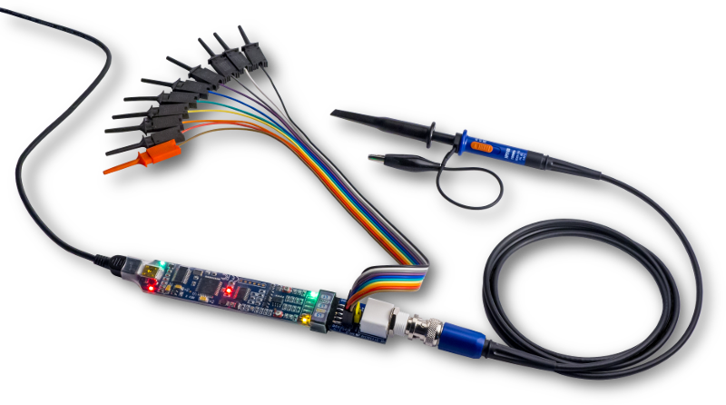
In addition to the BNC input for CHA, both analog channels appear on the header.
Analog (or logic) signals connected via any of the analog inputs are routed to BitScope Micro's logic channels 6 and 7 via its built-in comparators.
This means it's possible to capture up to 8 logic channels at once where two channels can be set to switch at an adjustable level which is ideal for unusual logic families or specialised signal standards (e.g. bipolar or negative voltage logic).
The BNC input is not just for waveform input either. A supplied header allows this connector to be used to capture logic (via L4) or output waveforms synthesized by BitScope Micro (via AWG) too.
A shorting plug allows the selection of the signal connected to the BNC socket. By default this is the CHA analog input. Additional plugs may be used to ground reference the analog inputs to prevent noise or crosstalk from open inputs.
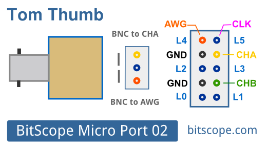
The shorting plug may also be used to route the waveform generator to the BNC socket and the built-in clock generator can be accessed via the 10-pin header.
The keycard shows how this is done.
The three-pin header allows the selection of CHA or the waveform generator (AWG) to the BNC socket. If the AWG is selected this signal can instead of connected to L4 under software control in BitScope Micro.
The two grounds adjacent to the analog inputs on the 10-pin header can be used to ground reference either analog input and connecting either analog input to an adjacent logic channel reduces the input impedance of the analog input from 1MΩ to 100kΩ which in can be very handy if the lower input impedance is required.
Programmable signal control provided by the BitScope Micro Diagnostic Port is available via MP02. For example the four logic channels can be set as active low pull-downs to configure a connected circuit for up to 16 states of operation.
| MP02 (100:1) | MP02 (10:1) | BS05 (1:1) |
| 110V | 11V | 1.1V |
| 350V | 35V | 3.5V |
| 520V | 52V | 5.2V |
| 1kV | 110V | 11V |
This table enumerates full scale voltage ranges available with MP02 when used with BitScope Micro and a 1:1, 10:1 and 100:1 probe.
It shows the maximum peak-to-peak signal that can be captured at full resolution with (8 bits in normal mode and up to 12 bits in macro mode).
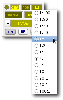
With BitScope DSO this is simply a matter of right-clicking the probe scale widget and choosing the right scale. In the example shown here, a probe scaling of 2:1 has already been chosen but the prescaler (1:5) is about to be selected instead.
Many scaling options are available to support the wide range of oscilloscope probes available because all of them can be used with BitScope Micro and MP02.
Coming soon are some mounting and case design ideas for MP02. The BNC sockets are supplied with ring nuts and washers so MP02 can be permanently mounted (with appropriate metalwork) and BitScope Micro plugged in as and when required.
| Feature | Specification |
| Analog Inputs (Standard Probe) | 1 |
| Analog Inputs (Pin Header) | 2 |
| Logic Inputs (3.3V/5V) | 6 |
| Comparator Channels | 2 (via analog inputs) |
| Waveform Generator | 1 (via L4) |
| Clock Generator | 1 (via L5) |
| Input Impedance (Analog) | 1M Ω / 20pF |
| Input Impedance (Digital) | 100k Ω / 5pF |
| Voltage Range (Direct) | -7.5 V ~ +10.8 V (1:1 probe) |
| Voltage Range (Scaled) | -75 V ~ +108 V (10:1 probe) |
| Device Connection | IDC-10 (Micro Port) |
| Power Requirement | None |
| Operating Temperature | 0 °C to 40 °C |
| Storage Requirements | -40 °C ~ +40 °C / 5 % ~ 95 % RH |
| Dimensions (W x D x H) | 20 x 60 x 20 mm |
| Weight (Net) | 16g |