| Designs |
|
This page describes the original BitScope design. The BS300 and the later models are similar, the BS300 schematics are here. The schematics below describe the main circuit. The next few pages walk you through the design. The sub-sections provide details of the analog circuits, A/D convertor and expansion POD.
If you have a PDF reader installed in your web browser, you can click on the thumbnails to see each schematic in detail. You can also can download all five sheets in one zip file from our download area. In addition to the main circuit, you can also view the schematics of our high speed A/D convertor. 
A/D Convertor and a circuit prototyping system called Proto POD 
Proto POD which connects to BitScope's Logic POD connector. 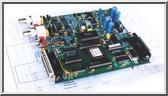
Main Board |
Copyright © 2023 BitScope Designs